EDIT: further images from this process were lost in a phone smash incident, sorry
Here’s a preliminary HOWTO from my recent external flashing of the BIOS ROM on a Lenovo X200 thinkpad (Wikipedia). The particular firmware flashed was a Libreboot build for this machine (instructions for X200 and details of the external flashing procedure) but anything goes (but anything may not be useful, though).
I’ll amend this HOWTO with more detailed instructions and pictures in the following days (warning: a prediction) to hopefully make it more complete and useful for the vary inhabitants of LibreBootLand.
Some parts
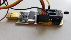
A programmer kit was bought on AliExpress for $4.20 containing a USB programmer board and an SOIC-8 clip which ended up not being used as the particular X200 had a SOIC-16 chip so a separately ordered SOIC-16 chip ($3.11) was used.
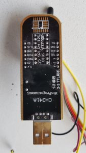
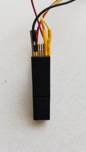
“MinProgramment” aka. CH341a Programmer
Buy: https://www.aliexpress.com/item/32898599200.html @ $4.20
The programmer is based on the WCH CH341a chip which is an USB <-> seriel/parallel/uart interface. The manufacturer WCH being WinChipHead aka. WCH (Nanjing QinHeng Electronics Co.,Ltd) (maybe also aka. WCH-IC (Jiangsu Qinheng Co., Ltd)). There are lots of options for buying board varieties based on the CH341a chip, to get you started here is a BangGood search and an AliExpress search.
Boards like this has also been described by others including a deduced schematic, EEVblog critique of the I/O pin power on similar boards (not yet confirmed whether that is true for this programmer too, I guess so, but at least one flashing done without damage) and a mention on hackaday of other board types.
There are a bunch of downloads from the WCH site regarding the chip including a Chinese datasheet, no English language documentation seems to be available from the manufacturer however. There are some English editions of the datasheet to be found, of unknown origin. They seem plausible enough to use, though. Somebody has attempted to collect documentation about the chip in a Git repository.


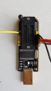
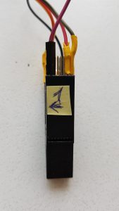
The SOIC-16 Clip (aka. Pomona 5252)
Buy: https://www.aliexpress.com/item/32869145935.html @ $3.11
To attach physically to the Macronix MX25L6405D flash memory chip in a SOIC-16 package present on the X200 in question (words are that this is the norm although the board can be populated with a SOIC-8 too) a clip that matches the pins of the SOIC-16 package is needed. I bought the one mentioned above for $3.11 at random from AliExpress and this worked fine. In the pictures the wiring is hooked up correctly to the programmer to allow for flashing as described below.


WARNING: Below is still a draft made from mental notes! Ask me if you need more information or check back soon (I promise).
Connections
6405 <-> CH341a
MISO<->MIOS (label error, should be MISO)
MOSI<->MOSI
CLK <-> CLK
CS <-> SS
GND <-> GND
First tried driving the the flash chip from VDD on ch341a but this was unsuccessful, no chip could be found, so the 6405 was hooked up to external 3.3v power supply with supply GND connected to GND on CH341a to align the ground potential between ch341a I/O supply and 6405 supply (important!).
Preparations
Machine being flashed
Update Embedded Controller
To get the latest ECP (Embedded Controller Program) from Lenovo (no free alternative exists) containing software for the MCU controlling low level hardware like battery charging/keyboard/backlight stuff you need to update the BIOS which also updates the ECP. Most recent version for X200 is “BIOS: 3.22 / ECP: 1.07“. This is not needed if you already have these versions on the machine, check current versions by pressing ThinkVantage during boot and choosing “Enter Setup”.
If your system has a Windows installation download and run the “BIOS Update Utility“executeable. Else you’ll need to get the “BIOS Update Bootable CD” and somehow get it on a CD and find a CD-ROM drive. Alternatively on a Linux system the CD file system can be extracted and added to Grub to be directly bootable. Below was done on an Ubuntu 16.04 system:
$ sudo apt install genisoimage syslinux
$ wget -q https://download.lenovo.com/ibmdl/pub/pc/pccbbs/mobiles/6duj48us.iso
$ geteltorito 6duj48us.iso > 6duj48us.img
Booting catalog starts at sector: 20
Manufacturer of CD: NERO BURNING ROM
Image architecture: x86
Boot media type is: harddisk
El Torito image starts at sector 27 and has 75776 sector(s) of 512 Bytes
Image has been written to stdout ….
$ sudo cp 6duj48us.im /boot
$ sudo cp /usr/lib/syslinux/memdisk /boot
$ sudo nano /etc/grub.d/40_custom
<add lines below to the end of file, preserve the “exec tail…” line>
menuentry “BIOS Update” {
linux16 /memdisk
initrd16 /6duj48us.im
}
$ sudo update-grub
Reboot, press <left shift> key while booting to access Grub, choose BIOS Update menu entry and follow the Lenovo update procedure. To start flashing it requires both a connected power supply and also a working, non-exhausted battery (!) mounted in the machine. This is tiresome for owners of worn out batteries…
Some notes about the flashing process can be found in the documentation of a patch set for the Lenovo BIOS.
Machine doing the programming
Install Flashrom
sudo apt install flashrom
ch341a support in flashrom
LibreBoot
Retrieve
Download the stable LibreBoot firmware: https://www.mirrorservice.org/sites/libreboot.org/release/stable/20160907/rom/grub/libreboot_r20160907_grub_x200_8mb.tar.xz
The brave will of course want to compile it themselves.
$ cd
$ wget https://www.mirrorservice.org/sites/libreboot.org/release/stable/20160907/rom/grub/libreboot_r20160907_grub_x200_8mb.tar.xz
--2019-06-07 07:35:21--  https://www.mirrorservice.org/sites/libreboot.org/release/stable/20160907/rom/grub/libreboot_r20160907_grub_x200_8mb.tar.xz
Resolving www.mirrorservice.org (www.mirrorservice.org)... 212.219.56.184, 2001:630:341:12::184
Connecting to www.mirrorservice.org (www.mirrorservice.org)|212.219.56.184|:443... connected.
HTTP request sent, awaiting response... 200 OK
Length: 1632800 (1,6M) [application/x-xz]
Saving to: ‘libreboot_r20160907_grub_x200_8mb.tar.xz’

libreboot_r20160907_grub_x200_8mb.tar.xz 100%[================================================================================>]   1,56M  --.-KB/s    in 0,1s

2019-06-07 07:35:21 (13,9 MB/s) - ‘libreboot_r20160907_grub_x200_8mb.tar.xz’ saved [1632800/1632800]
$ tar tf libreboot_r20160907_grub_x200_8mb.tar.xz
libreboot_r20160907_grub_x200_8mb/
libreboot_r20160907_grub_x200_8mb/x200_8mb_deqwertz_txtmode.rom
libreboot_r20160907_grub_x200_8mb/x200_8mb_esqwerty_txtmode.rom
libreboot_r20160907_grub_x200_8mb/x200_8mb_frazerty_txtmode.rom
libreboot_r20160907_grub_x200_8mb/x200_8mb_frdvbepo_txtmode.rom
libreboot_r20160907_grub_x200_8mb/x200_8mb_itqwerty_txtmode.rom
libreboot_r20160907_grub_x200_8mb/x200_8mb_svenska_txtmode.rom
libreboot_r20160907_grub_x200_8mb/x200_8mb_ukdvorak_txtmode.rom
libreboot_r20160907_grub_x200_8mb/x200_8mb_ukqwerty_txtmode.rom
libreboot_r20160907_grub_x200_8mb/x200_8mb_usdvorak_txtmode.rom
libreboot_r20160907_grub_x200_8mb/x200_8mb_usqwerty_txtmode.rom
libreboot_r20160907_grub_x200_8mb/x200_8mb_deqwertz_vesafb.rom
libreboot_r20160907_grub_x200_8mb/x200_8mb_esqwerty_vesafb.rom
libreboot_r20160907_grub_x200_8mb/x200_8mb_frazerty_vesafb.rom
libreboot_r20160907_grub_x200_8mb/x200_8mb_frdvbepo_vesafb.rom
libreboot_r20160907_grub_x200_8mb/x200_8mb_itqwerty_vesafb.rom
libreboot_r20160907_grub_x200_8mb/x200_8mb_svenska_vesafb.rom
libreboot_r20160907_grub_x200_8mb/x200_8mb_ukdvorak_vesafb.rom
libreboot_r20160907_grub_x200_8mb/x200_8mb_ukqwerty_vesafb.rom
libreboot_r20160907_grub_x200_8mb/x200_8mb_usdvorak_vesafb.rom
libreboot_r20160907_grub_x200_8mb/x200_8mb_usqwerty_vesafb.rom
libreboot_r20160907_grub_x200_8mb/ChangeLog
libreboot_r20160907_grub_x200_8mb/NEWS
libreboot_r20160907_grub_x200_8mb/version
libreboot_r20160907_grub_x200_8mb/versiondate
$
Customise MAC address
As the MAC address of the ethnernet PHY is stored in the flash, yo have your X200 ethernet MAC address correspond to the sticker on the back of the machine, and also avoid a potential but improbable DHCP/ARP conflict, the MAC address from the label/ifconfig from the existing system must be embedded into the flash file that we are going to program into the flash chip.
For this a tool called ich9gen is needed, this is a part of the libreboot repository and we need to build it ourselves.
Build ich9gen
$ git clone https://notabug.org/libreboot/libreboot
Cloning into 'libreboot'...
remote: Counting objects: 29080, done.
remote: Compressing objects: 100% (9855/9855), done.
remote: Total 29080 (delta 18748), reused 27899 (delta 18057)
Receiving objects: 100% (29080/29080), 63.90 MiB | 11.13 MiB/s, done.
Resolving deltas: 100% (18748/18748), done.
Checking connectivity... done.
$ cd libreboot/projects/ich9gen/sources
$ make
gcc -I. -Wall -Wextra -g -std=c99 -c src/ich9deblob.c -o obj/ich9deblob.o
gcc -I. -Wall -Wextra -g -std=c99 -c src/common/descriptor_gbe.c -o obj/common/descriptor_gbe.o
gcc -I. -Wall -Wextra -g -std=c99 -c src/descriptor/descriptor.c -o obj/descriptor/descriptor.o
gcc -I. -Wall -Wextra -g -std=c99 -c src/gbe/gbe.c -o obj/gbe/gbe.o
gcc -I. -Wall -Wextra -g -std=c99 -c src/common/x86compatibility.c -o obj/common/x86compatibility.o
gcc -I. -Wall -Wextra -g -std=c99 obj/ich9deblob.o obj/common/descriptor_gbe.o \
	obj/common/x86compatibility.o obj/descriptor/descriptor.o obj/gbe/gbe.o \
	 -o ich9deblob
gcc -I. -Wall -Wextra -g -std=c99 -c src/ich9gen.c -o obj/ich9gen.o
gcc -I. -Wall -Wextra -g -std=c99 -c src/ich9gen/mkdescriptor.c -o obj/ich9gen/mkdescriptor.o
gcc -I. -Wall -Wextra -g -std=c99 -c src/ich9gen/mkgbe.c -o obj/ich9gen/mkgbe.o
gcc -I. -Wall -Wextra -g -std=c99 obj/ich9gen.o obj/ich9gen/mkdescriptor.o obj/ich9gen/mkgbe.o \
 obj/common/descriptor_gbe.o \
	obj/common/x86compatibility.o obj/descriptor/descriptor.o obj/gbe/gbe.o \
	 -o ich9gen
gcc -I. -Wall -Wextra -g -std=c99 -c src/demefactory.c -o obj/demefactory.o
gcc -I. -Wall -Wextra -g -std=c99 obj/demefactory.o obj/common/descriptor_gbe.o \
	obj/common/x86compatibility.o obj/descriptor/descriptor.o obj/gbe/gbe.o \
	 -o demefactory
$
Run ich9gen
Running ich9gen itself generates the flash descriptor (fd) header including possible configuration section where the MAC address is stored for the gigabit ethernet (gbe) PHY onboard the ICH9 chipset. When run six 12 KiB files for respectively 4, 8 and 16 MiB binary images and chipsets including (gbe) and excluding (nogbe) gigabit ethernet PHY are generated.
“aa:bb:cc:dd:ee:ff” in the commandline should be replaced with the actual 12 hex digits from the label on the machine or by running ifconfig on the machine using the existing Lenovo BIOS.
$ cd ~/libreboot_r20160907_grub_x200_8mb/
$ ~/libreboot/projects/ich9gen/sources/ich9gen --macaddress aa:bb:cc:dd:ee:ff
You selected to change the MAC address in the Gbe section. This has been done.

The modified gbe region has also been dumped as src files: mkgbe.c, mkgbe.h
To use these in ich9gen, place them in src/ich9gen/ and re-build ich9gen.

descriptor and gbe successfully written to the file: ich9fdgbe_4m.bin
Now do: dd if=ich9fdgbe_4m.bin of=libreboot.rom bs=1 count=12k conv=notrunc
(in other words, add the modified descriptor+gbe to your ROM image)

descriptor and gbe successfully written to the file: ich9fdgbe_8m.bin
Now do: dd if=ich9fdgbe_8m.bin of=libreboot.rom bs=1 count=12k conv=notrunc
(in other words, add the modified descriptor+gbe to your ROM image)

descriptor and gbe successfully written to the file: ich9fdgbe_16m.bin
Now do: dd if=ich9fdgbe_16m.bin of=libreboot.rom bs=1 count=12k conv=notrunc
(in other words, add the modified descriptor+gbe to your ROM image)

descriptor successfully written to the file: ich9fdnogbe_4m.bin
Now do: dd if=ich9fdnogbe_4m.bin of=yourrom.rom bs=1 count=4k conv=notrunc
(in other words, add the modified descriptor to your ROM image)

descriptor successfully written to the file: ich9fdnogbe_8m.bin
Now do: dd if=ich9fdnogbe_8m.bin of=yourrom.rom bs=1 count=4k conv=notrunc
(in other words, add the modified descriptor to your ROM image)

descriptor successfully written to the file: ich9fdnogbe_16m.bin
Now do: dd if=ich9fdnogbe_16m.bin of=yourrom.rom bs=1 count=4k conv=notrunc
(in other words, add the modified descriptor to your ROM image)
Apply Flash Descriptor to Binary
$ cd ~/libreboot_r20160907_grub_x200_8mb/
$ cp -v x200_8mb_usqwerty_vesafb{,_customised}.rom
'x200_8mb_usqwerty_vesafb.rom' -> 'x200_8mb_usqwerty_vesafb_customised.rom'
$ dd if=ich9fdgbe_8m.bin of=x200_8mb_usqwerty_vesafb_customised.rom bs=1 count=12k conv=notrunc
12288+0 records in
12288+0 records out
12288 bytes (12 kB, 12 KiB) copied, 0,0299453 s, 410 kB/s
$
Procedure
Programmer Setup Validation / Lenovo BIOS backup
flashrom -p ch341a_spi -c MX25L6405D -r rom1.bin
flashrom -p ch341a_spi -c MX25L6405D -r rom2.bin
flashrom -p ch341a_spi -c MX25L6405D -r rom3.bin
flashrom -p ch341a_spi -c MX25L6405D -r rom4.bin
flashrom -p ch341a_spi -c MX25L6405D -r rom5.bin
cmp rom{1,2}.bin
cmp rom{1,3}.bin
cmp rom{1,4}.bin
cmp rom{1,5}.bin
Flashing
$ sudo flashrom -p ch341a_spi -c MX25L6405D -w ~/libreboot_r20160907_grub_x200_8mb/x200_8mb_usqwerty_vesafb_customised.rom
$
Accounts of LibreBoot Flashing
Embedded Controller (EC) information