Investigating further on the BBB boot issue described in this earlier post and following discussion in the mailinglist, here is a test of another BBB modification trying to remedy this.
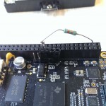
This time the modification is done on the non-cpu side of U15 (75LVC2G241 buffer/driver), where the buffered uart0 input (B_UART0_RX) is kept stable using a voltage divider. B_UART0_RX is already pulled low by a 100k resistor, but adding another 82k5 ohms pulling against 3,3v makes up a voltage divider, keeping input 1A on U15 stable at all times at approx. half (~55%) of the voltage between VDD_3V3B and DGND. At stable 3,3V that voltage will be 3.3V*100k/(82k5+100k)= 1.81V (EDIT: first edition of this post erroneously stated the voltage drop of ~1.4V over the pull up as the B_UART0_RX’s voltage level).
Beware that this modification might affect the functionality of uart0 rx capability. I’ll probably test this some time soon (TM) when I got access to my TTL<->USB converter.
These results are summed up in this post on the BBB mailinglist.
Results
Providing a stable B_UART0_RX at 1.8V results in a booting BBB in every test case!
The third picture below shows an easy and relatively safe way to make this a permanent fix on the backside of the BBB. It places a resistor (this one is 82k5 ohm ) between VDD_3V3B from terminal 5 on the non-populated P2 header marked as “CTI JTAG, DNI” and the B_UART0_RX signal on J2 (UART0 Serial Port) pin 4.
Failure Rates
- Unmodified BBB (DUT#1): 4 fails/65 boots= 6,2%
- Fixed B_UART0_RX at ~1.8v (DUT#2): 0 fails/50 boots= 0,0%
- Strong pull down on B_UART0_RX (DUT#3): 3 fails/50 boots= 6.0%
Pictures
-

-
Mocked up voltage divider keeping B_UART0_RX stable.
-

-
Test equipment and setup.
-

-
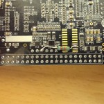
First attempt at a more robust modification on the solder side of the PCB.
Detailed Test Report
(formatted in nice emacs org-mode)
* BBB boot lockup test report 2
** Equipment*** Device Under Test #1
Unmodified Beaglebone Black (BBB) produced by Element 14
(PCB REV B6, serial EM-400524+XA6001961, marked "Element 14").
*** Device Under test #2
Modify DUT#1 by applying a 82k5 ohm pull up resistor from J1,
pin 4 (B_UART0_RX, U15-pin 2, signal 1A) to P8, pin 4 (VDD_3V3B),
effectively creating a voltage divider with existing pull down
resistor R165 (100k ohm) fixing voltage on B_UART0_RX to
3.3V*100k/(82k5+100k)= 1.81V.
*** Device Under Test #3
Modify DUT#1 by applying a 82k5 ohm pull down resistor from J1,
pin 4 (B_UART0_RX, U15-pin 2, signal 1A) to P8, pin 1 (DGND),
thus forming a stronger pull down on B_UART0_RX with resistive
value of 1/(1/100k+1/82k5)= 45k2 ohm
*** Power Supply Unit
 Huawei HW-050200E3W, output 5V 2A, USB A-connector. Danish plug.
 Sourced from Huawei E589 mobile wifi.
*** Power Cable
20 cm no-name USB A male connector to USB Mini-B male connector.
** Test 1 Procedure
Insert PSU into mains socket. Test boot capability of DUT#1 by
inserting the USB A connector into the mains socket adaptor while
keeping the USB Mini-B connector inserted into the BBB. Then verify
that the power led light up, and note whether boot succeeded or
failed by watching if USR0-USR3 lights up indicating boot. Then
remove the A connector from the mains adaptor wait 3 seconds and repeat.
Results can be seen in section Test Results, column Test 1.
** Test 2 Procedure
Repeat Test 1 procedure using DUT#2.
Results can be seen in section Test Results, column Test 2.
** Test 3 procedure
Repeat Test 1 procedure using DUT#3.
Results can be seen in section Test results, column Test 3.
** Interpretation
DUT#1 failure rate= 4 fails/65 boots= *6,2%*
DUT#2 failure rate= 0 fails/50 boots= *0,0%*
DUT#3 failure rate= 3 fails/50 boots= *6.0%*
Test 2 in reference to Test 1 shows that fixing B_UART0_RX to
1.4v using a voltage divider increases the system boot success
rate from 94% to 100%. Though the modification might affect the
functionality of uart0 rx capability.
Test 3 shows that forming a stronger pull down on B_UART0_RX
(100k->45k), dosn't change the failure rate as might be expected.
This suggest that some strong (internal?) signal that a pull
down in itself can't correct is driving the the 75LVC2G241's
1A input sometime during powerup.
** Test results
 | Boot no. | Test 1  | Test 2 | Test 3  |
 |        1 | boot    | boot   | boot    |
 |        2 | boot    | boot   | boot    |
 |        3 | boot    | boot   | boot    |
 |        4 | boot    | boot   | boot    |
 |        5 | boot    | boot   | boot    |
 |        6 | boot    | boot   | boot    |
 |        7 | boot    | boot   | boot    |
 |        8 | boot    | boot   | boot    |
 |        9 | boot    | boot   | boot    |
 |       10 | boot    | boot   | boot    |
 |       11 | boot    | boot   | boot    |
 |       12 | boot    | boot   | boot    |
 |       13 | boot    | boot   | boot    |
 |       14 | boot    | boot   | boot    |
 |       15 | boot    | boot   | boot    |
 |       16 | boot    | boot   | boot    |
 |       17 | boot    | boot   | boot    |
 |       18 | boot    | boot   | boot    |
 |       19 | boot    | boot   | boot    |
 |       20 | boot    | boot   | boot    |
 |       21 | no boot | boot   | boot    |
 |       22 | boot    | boot   | boot    |
 |       23 | boot    | boot   | boot    |
 |       24 | boot    | boot   | boot    |
 |       25 | boot    | boot   | boot    |
 |       26 | boot    | boot   | boot    |
 |       27 | boot    | boot   | boot    |
 |       28 | boot    | boot   | boot    |
 |       29 | boot    | boot   | boot    |
 |       30 | boot    | boot   | boot    |
 |       31 | boot    | boot   | boot    |
 |       32 | boot    | boot   | boot    |
 |       33 | boot    | boot   | no boot |
 |       34 | boot    | boot   | no boot |
 |       35 | boot    | boot   | boot    |
 |       36 | boot    | boot   | boot    |
 |       37 | boot    | boot   | boot    |
 |       38 | no boot | boot   | boot    |
 |       39 | boot    | boot   | boot    |
 |       40 | boot    | boot   | boot    |
 |       41 | boot    | boot   | boot    |
 |       52 | boot    | boot   | boot    |
 |       53 | boot    | boot   | boot    |
 |       44 | boot    | boot   | no boot |
 |       45 | no boot | boot   | boot    |
 |       46 | boot    | boot   | boot    |
 |       47 | boot    | boot   | boot    |
 |       48 | boot    | boot   | boot    |
 |       49 | boot    | boot   | boot    |
 |       50 | boot    | boot   | boot    |
 |       51 | boot    |        |         |
 |       52 | boot    |        |         |
 |       53 | boot    |        |         |
 |       54 | boot    |        |         |
 |       55 | boot    |        |         |
 |       56 | boot    |        |         |
 |       57 | boot    |        |         |
 |       58 | boot    |        |         |
 |       59 | boot    |        |         |
 |       60 | boot    |        |         |
 |       61 | boot    |        |         |
 |       62 | boot    |        |         |
 |       63 | boot    |        |         |
 |       64 | boot    |        |         |
 |       65 | no boot |        |         |